Objectives
Individual Assignment
1) Design, build, and connect wired or wireless node(s) with network or bus addresses
Group Assignment
1)Send a message between two projects.
What is 2.4 GHz ISM band?
2.4 GHz band is one of the Industrial, Scientific, and Medical (ISM) bands reserved internationally for the use of unlicensed low-powered devices. Examples are Cordless phones, Bluetooth devices, near field communication (NFC) devices, and wireless computer networks (WiFi) all use the ISM frequencies.
The operating voltage of the module is from 1.9 to 3.6V, but the good news is that the logic pins are 5-volt tolerant, so we can easily connect it to an Arduino or any 5V logic microcontroller without using any logic level convert.
The nRF24L01+ transceiver module communicates over a 4-pin Serial Peripheral Interface (SPI) with a maximum data rate of 10Mbps.The SPI bus uses a concept of a Master and Slave, Unlike the I2C bus the number of slaves on the SPI bus is limited.
Here are complete specifications:
Frequency Range 2.4 GHz ISM Band
Maximum Air Data Rate 2 Mb/s
Modulation Format GFSK
Max. Output Power 0 dBm
Operating Supply Voltage 1.9 V to 3.6 V
Max. Operating Current 13.5mA
Min. Current(Standby Mode) 26µA
Logic Inputs 5V Tolerant
Communication Range 800+ m (line of sight)
The nRF24L01+ transceiver module transmits and receives data on a certain frequency called Channel. Also in order for two or more transceiver modules to communicate with each other, they need to be on the same channel. This channel could be any frequency in the 2.4 GHz ISM band.
Each channel occupies a bandwidth of less than 1MHz. This gives us 125 possible channels with 1MHz spacing. So, the module can use 125 different channels which give a possibility to have a network of 125 independently working modems in one place.
Remember when scaling up?
The channel occupies a bandwidth of less than 1MHz at 250kbps and 1Mbps air data rate. However at 2Mbps air data rate, 2MHz bandwidth is occupied .So, to ensure non-overlapping channels and reduce cross-talk in 2Mbps mode, you need to keep 2MHz spacing between two channels.
Also Check out this
Multiceiver Network-https://www.instructables.com/NRF24L01-Multiceiver-Network/
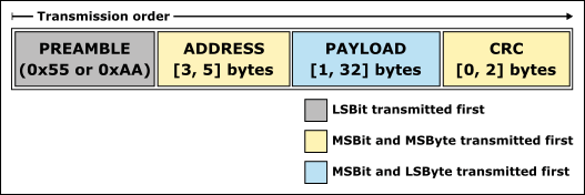
The nRF24L01+ transceiver module uses a packet structure known as Enhanced ShockBurst
1. It allows for variable length payloads with a payload length specifier, meaning payloads can vary from 1 to 32 bytes.
2.It provides each sent packet with a packet ID, which allows the receiving device to determine whether a message is new or whether it has been retransmitted (and thus can be ignored).
3.Each message can request an acknowledgement to be sent when it is received by another device.
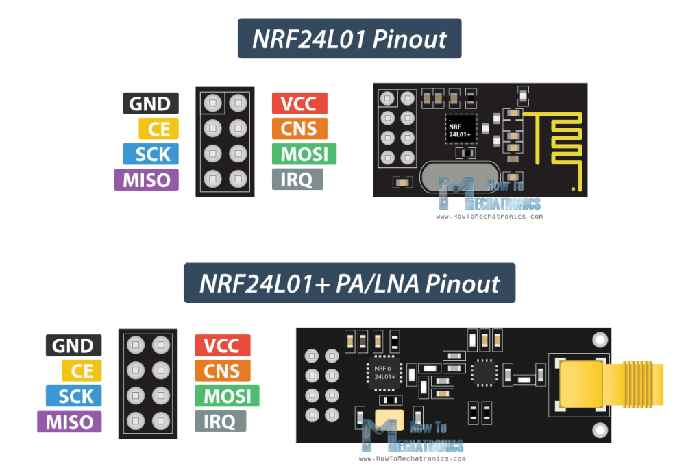
VCC - This can be anywhere from 1.9 to 3.9 volts. Remember connecting it to 5V pin will likely destroy your nRF24L01+ module!
CE (Chip Enable)- is an active-HIGH pin. When selected the nRF24L01 will either transmit or receive, depending upon which mode it is currently in.
CSN (Chip Select Not) is an active-LOW pin and is normally kept HIGH. When this pin goes low, the nRF24L01 begins listening on its SPI port for data and processes it accordingly.
SCK (Serial Clock) accepts clock pulses provided by the SPI bus Master.
MOSI (Master Out Slave In) is SPI input to the nRF24L01.
MISO (Master In Slave Out) is SPI output from the nRF24L01.
I used ATtiny 1614 and made the board with pin-out as 3.3v(USED a voltage regulator ...vcc to module),CE,CNS,SCK,MISO and MOSI.And 2 LEDS.
Reduce Power Supply Noise
An RF circuit that generates a Radio Frequency (RF) signal, is very sensitive to power supply noise.it is advised to place a 10 µf filter capacitor across the power supply.
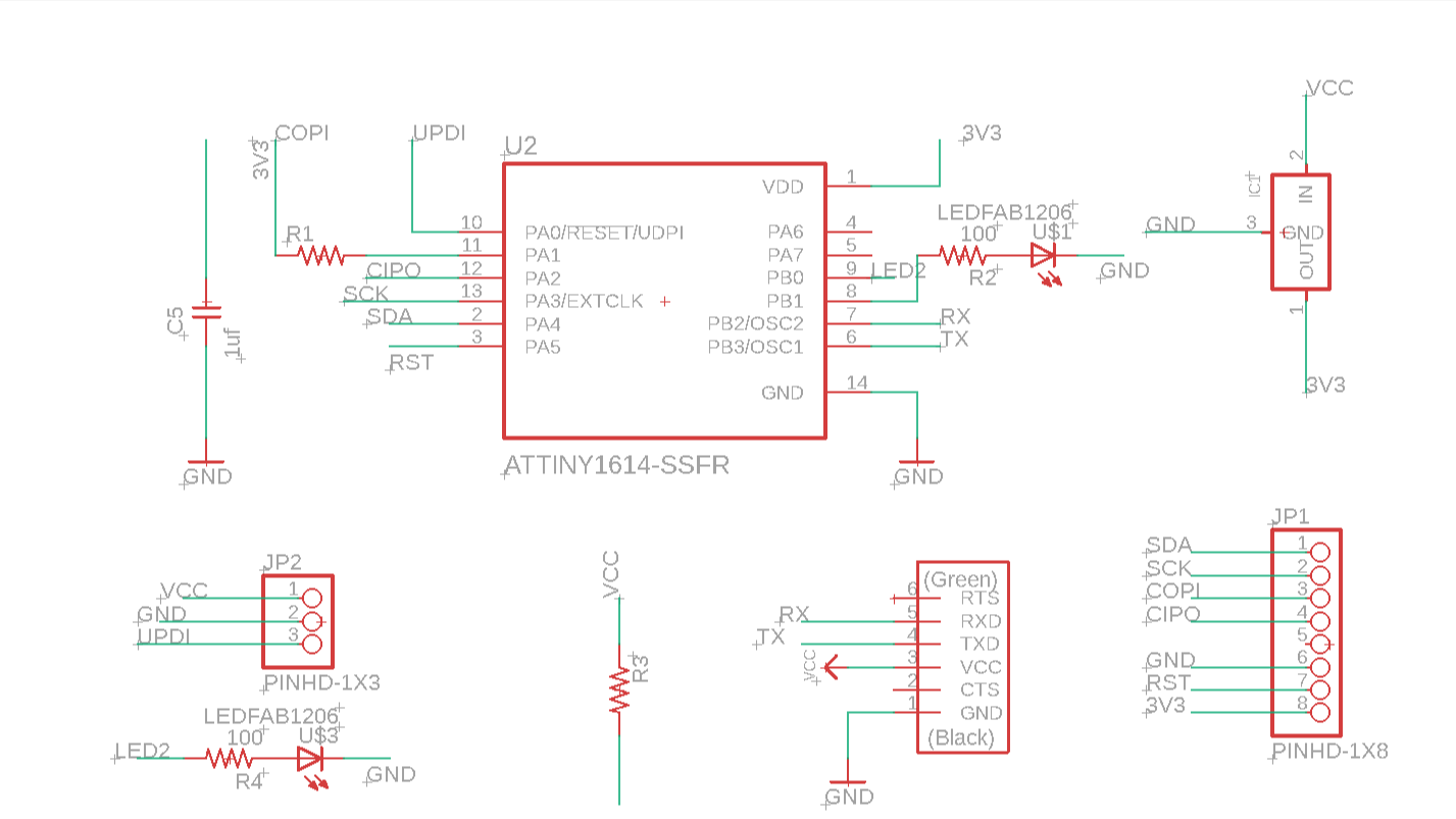
Schematic
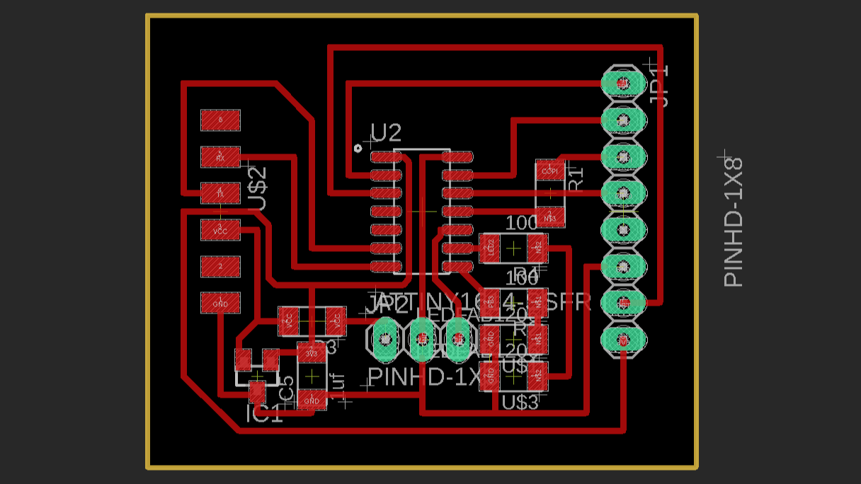
Board Routed.
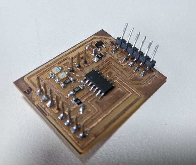
Milled and Soldered Board
One of the popular libraries is RF24.
https://github.com/nRF24/RF24
To install it, open the Arduino IDE, go to Sketch > Include Library > Add .ZIP Library, and then select the RF24-master file that you just downloaded.
Important this to configure.
1.Include Libraries
SPI.h
nRF24L01.h
nRF24L01.h
2.create an RF24 object.( CEpin, CSN pin)
RF24 radio(1, 0);
3.Address through which two modules communicate.
const byte address[6] = "00001";
We can change the value of this address to any 5-letter string such as “node1”. The address is necessary if you have a few modules in a network. Thanks to the address, you can choose a particular module to which you are interested in communicating, so in our case we will have the same address for both the transmitter and the receiver.
For detailed documentation of library visit -https://nrf24.github.io/RF24/
//Include Libraries
#include <SPI.h
#include <nRF24L01.h
#include <RF24.h>
char c;
String s;
//create an RF24 object
RF24 radio(1, 0); // CE, CSN
//address through which two modules communicate.
const byte address[6] = "00001";
void setup()
{
while (!Serial);
Serial.begin(9600);
radio.begin();
//Set module as receiver
radio.startListening();
}
void loop()
{
while (Serial.available() > 0)
{
c = Serial.read();
s = s + c;
}
if (s != "")
{
radio.openWritingPipe(address);
radio.stopListening();
Serial.print("Abel :");
Serial.println(s);
//Send message to receiver
char text[32] = "Abel : ";;
for (byte i = 0; i < s.length(); i++)
{
text[i + 7] = s[i];
}
radio.write(&text, sizeof(text));
s = "";
radio.openReadingPipe(0, address);
radio.startListening();
}
if (radio.available() > 0)
{
char text[32] = {0};
radio.read(&text, sizeof(text));
Serial.println(text);
}
delay(1000);
}
So after programming my board I connected a Ardino Uno and connected the same module as the confg. below and programmed in same address(0001) and different name in front of the text sent.
As nRF24L01+ transceiver module require a lot of data transfer, they will give the best performance when connected up to the hardware SPI pins on a microcontroller. The hardware SPI pins are much faster than ‘bit-banging’ the interface code using another set of pins.
Arduino Uno
MOSI-11
MISO -12
SCK -13
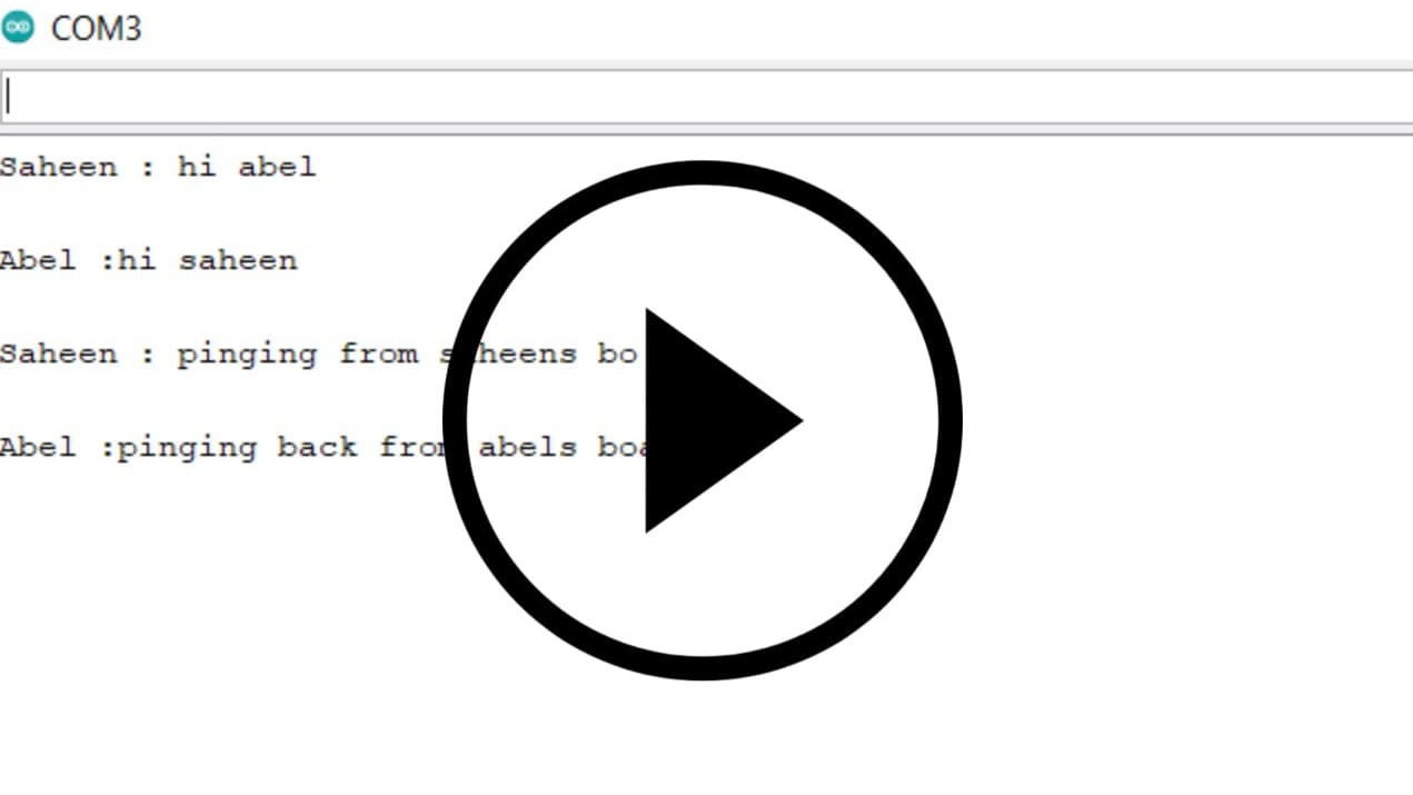
hurrrayyyyy we can talk each other via radio.
Improvements And Suggesions:-
Change your channel frequency
Another potential source of noise for an RF circuit is the outside environment, especially if you have neighboring networks set on the same channel or interference from other electronics.To prevent these signals from causing issues, using the highest 25 channels,Reason for this is WiFi uses most of the lower channels.
Lower Data Rate
receiver at 250Kbps is nearly 10 times more sensitive than at 2Mbps. That means the receiver can decode a signal that is 10 times weak.So, lowering the data rate can significantly improve the range
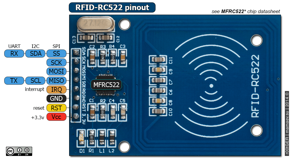
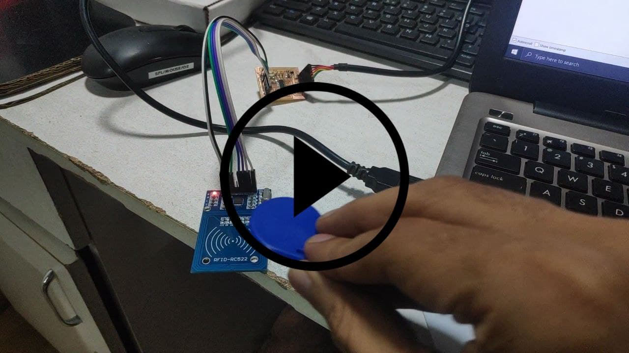
RFID PIN out.
How RFID Works?
The RC522 RFID Reader module is designed to create a 13.56MHz electromagnetic field that it uses to communicate with the RFID tags (ISO 14443A standard tags). The reader can communicate with a microcontroller over a 4-pin Serial Peripheral Interface (SPI) with a maximum data rate of 10Mbps. It also supports communication over I2C and UART protocols.
The module comes with an interrupt pin. It is handy because instead of constantly asking the RFID module “is there a card in view yet? “, the module will alert us when a tag comes into its vicinity.
The operating voltage of the module is from 2.5 to 3.3V
Frequency Range 13.56 MHz ISM Band
Host Interface SPI / I2C / UART
Operating Supply Voltage 2.5 V to 3.3 V
Max. Operating Current 13-26mA
Min. Current(Power down) 10µA
Logic Inputs 5V Tolerant
Read Range 5 cm
MFRC522 library which simplifies reading from and writing to RFID tags
https://github.com/miguelbalboa/rfid
#include <SPI.h
#include <MFRC522.h>
#define SS_PIN 0
#define RST_PIN 1
#define KEY_RETURN 0xB0 //The hex value for the return key is 0xB0.
MFRC522 mfrc522 ( SS_PIN, RST_PIN ) ;
char Enter = KEY_RETURN; //Return key is declared as Enter.
String readid;
String card1 = "a6c15673"; //Change this value to the UID of your card.
void setup( )
{
Serial.begin(115200);
SPI.begin();
mfrc522.PCD_Init();
pinMode(7, OUTPUT);
pinMode(6, OUTPUT);
}
void temp(byte *buffer, byte bufferSize)//function to store card uid as a string datatype.
{
readid = "";
for (byte i = 0; i < bufferSize; i++)
{
readid = readid + String(buffer[i], HEX);
}
}
void loop( )
{
if (!mfrc522.PICC_IsNewCardPresent())
{
return;
}
if (!mfrc522.PICC_ReadCardSerial())
{
return;
}
// mfrc522.PICC_DumpToSerial(&(mfrc522.uid)); // Display card details in serial Monitor.
temp(mfrc522.uid.uidByte, mfrc522.uid.size);
if (readid == card1)
{
Serial.println("haii abel");
digitalWrite(6, HIGH); // turn the LED on (HIGH is the voltage level)
delay(2000); // wait for a second
digitalWrite(6, LOW); // turn the LED off by making the voltage LOW
delay(2000); // wait for a
}
else
{ Serial.println("who the f*ck are you");
digitalWrite(7, HIGH); // turn the LED on (HIGH is the voltage level)
delay(2000); // wait for a second
digitalWrite(7, LOW); // turn the LED off by making the voltage LOW
delay(2000);
}
}
Person Identified. ;)
https://www.arduino.cc/reference/en/language/functions/usb/keyboard/
https://github.com/arduino-libraries/Keyboard
#include< Keyboard.h>
#include <SPI.h
#include <MFRC522.h>
#define SS_PIN 10
#define RST_PIN 5
#define KEY_RETURN 0xB0 //The hex value for the return key is 0xB0.
MFRC522 mfrc522 ( SS_PIN, RST_PIN ) ;
char Enter = KEY_RETURN; //Return key is declared as Enter.
String readid;
String card1 = "a6c15673"; //Change this value to the UID of your card.
void setup( )
{
Serial.begin(9600);
Keyboard.begin();
SPI.begin();
mfrc522.PCD_Init();
}
void temp(byte *buffer, byte bufferSize)//function to store card uid as a string datatype.
{
readid = "";
for (byte i = 0; i < bufferSize; i++)
{
readid = readid + String(buffer[i], HEX);
}
}
void loop( )
{
if (!mfrc522.PICC_IsNewCardPresent())
{
return;
}
if (!mfrc522.PICC_ReadCardSerial())
{
return;
}
mfrc522.PICC_DumpToSerial(&(mfrc522.uid)); // Display card details in serial Monitor.
temp(mfrc522.uid.uidByte, mfrc522.uid.size);
if (readid == card1)
{
Keyboard.print(" "); //Press the Space key.
Keyboard.releaseAll(); //Release key.
delay(100);
Keyboard.print("8991"); // Change this value to your Windows PIN/Password.
Keyboard.releaseAll();
}
else
{
return;
}
}
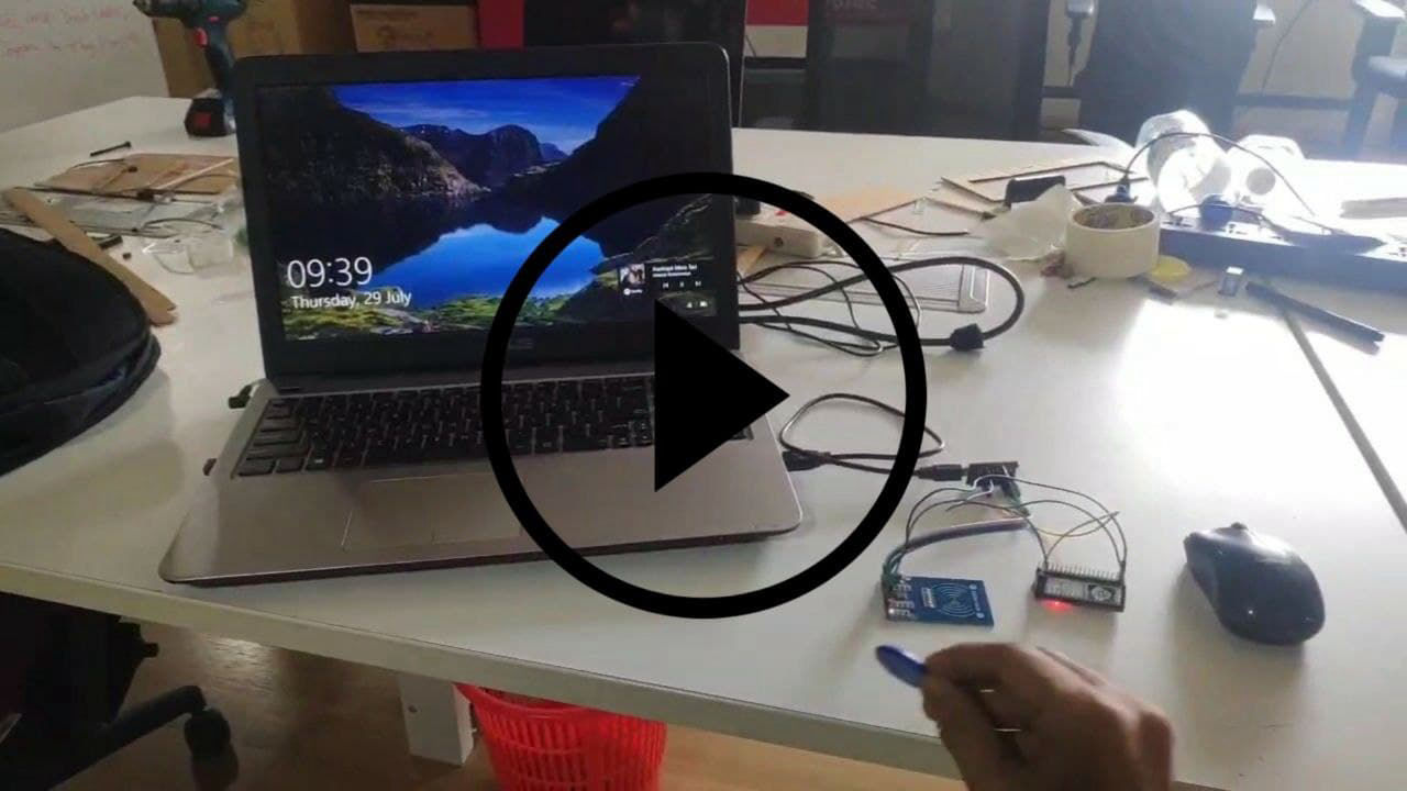
Windows Unlock And Card INFo Dumping
Built with Mobirise site theme